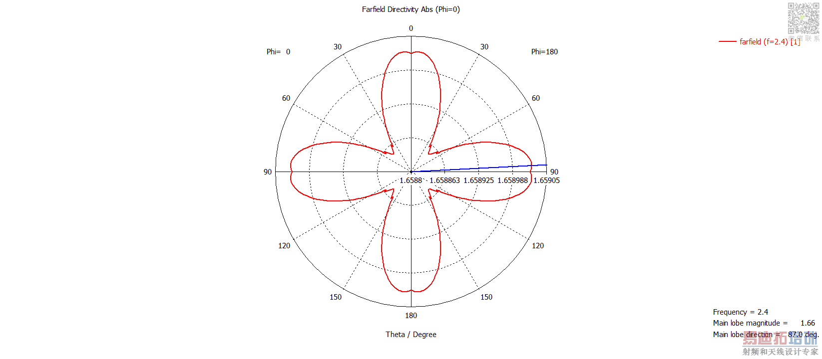
CST MWS dipole radiation pattern discrepancy
Hi!
I designed a simple (y-oriented) half-wave dipole excited using a discrete port in CST MWS.
I had a look at the radiation pattern and it seems just fine as compared to analytical solution. It returns a directivity of 1.6 and E-plane HPBW of 78 degrees.
The issue I am having is the radiation pattern in the H-plane shows ripples in the polar plot attached. Now, the ripples are of a very small magnitude (ranging from 1.658-1.659)

Why are there ripples (although of extremely small magnitude) present though? It also seems to exhibit perfect (up-down, left-right) symmetry.
I initially thought this was due to the cylinder model segments defined, but I get the same symmetry even if I increased the number of segments of cylinder model to say 30, or a smooth cylinder with zero segments.
Increasing the mesh count also does not seem to fix the "problem".
Any feedback and input is very much appreciated!
this scale of ripple could be because of program error and by the way when you use symmetric planes it gain simulation speed and causes small error. because by the way its not perfect aprox.
Hi redcrystalline,
Thanks for your comment. I get that "error" even when I remove symmetry planes.
I am narrowing it down to program error and possibly the interpolation code used to define the radiation pattern. I shall look more into it! (*I shouldn't be wasting so much time for an accuracy of 0.001 but I am very interested to find out!)
Thanks again!
So interesting
Great Spirit
Be care about these Hints:
Use open/add space boundary conditions;(you could increase it an see what happens[i guess program default is landa/4])
Use vacuum or air background materials
I just thought I'd pick this up where I left off previously. I found that this "error" is due to a phenomenon known as numerical dispersion (an inherent trait of FDTD programs).
hi gyz182,
you can set the symmetric planes as default and try adaptive mesh refinement.
Hi pragash thanks for your input. I've set no symmetry planes as it is a very small problem and solver speed isn't really a problem. I've tried increasing mesh cells, and adaptive mesh refinement.
As the mesh increases (more fine), there's less degree of "error" but it still exists and based on my understanding, will always be there due to numerical dispersion (light travelling at different distance,given the mesh size and dimension).
This simulation was done using the transient solver, based on the FDTD method which is affected by numerical dispersion.
I've also tried using the integral solver, which gives an entirely different "shape" to the far-field. It is omni-directional, but when it is zoomed in as shown in graphs above, the shape no longer has symmetry and is generally in very small order of about 0.01.
Time to hit the books on integral equation solvers.


