help reading CST simuletion readout i.e. "effic"
Hi to all
I'm running CTT simulation of an antenna
On the 3D simulation there are this two parameters:
Red. Effic. & Tot. effic
I think that effic stands for efficiency
If so : G = e*D
But then I'm having hard time getting the "logic"
Im running on the same antenna simulation different using frequencies
Getting the attached readout
Please help me understand the "effic" values
Thanks a lot for any help
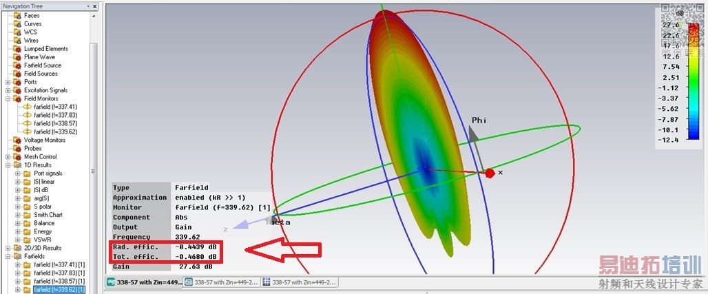
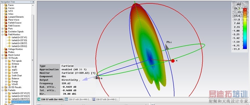
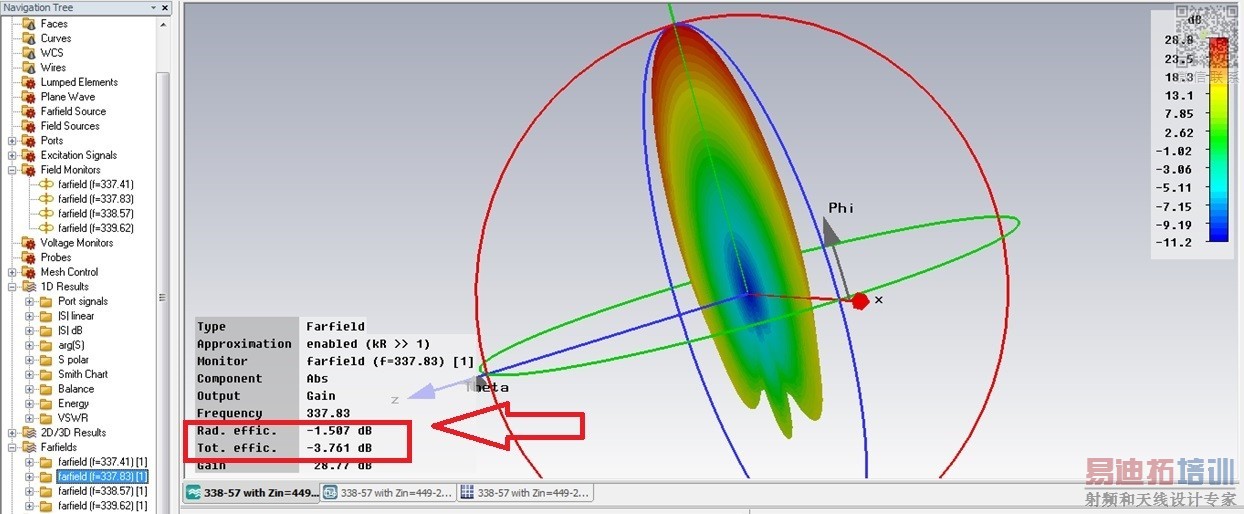
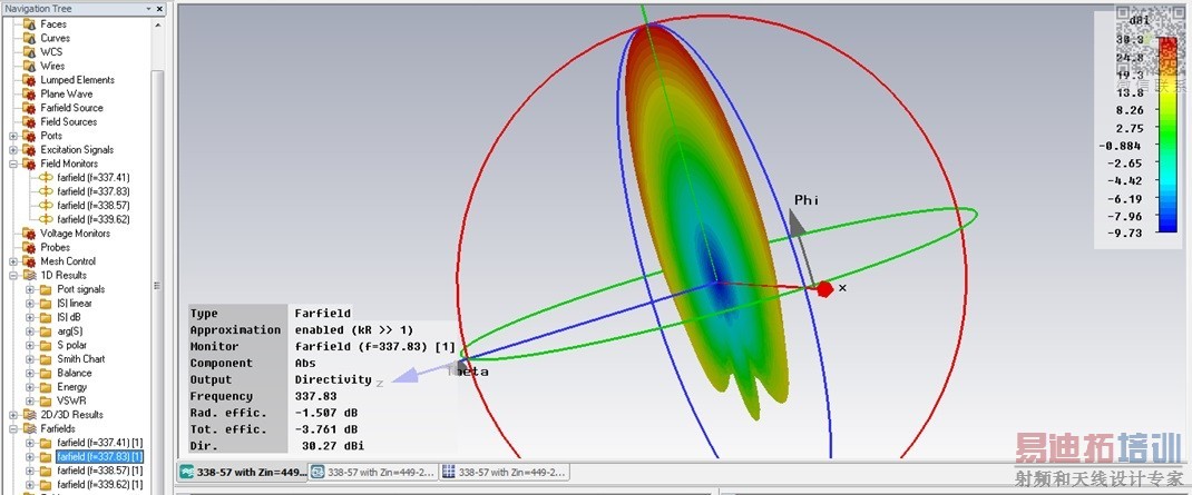
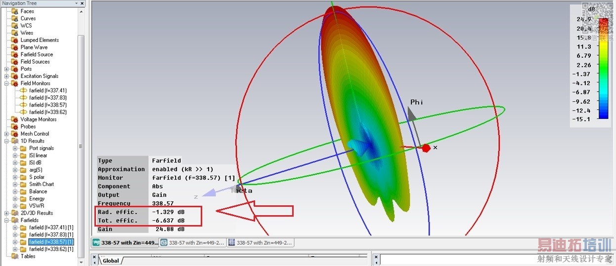
Simulation output:
Antenna 3D simulation at 339.62 GHz:
Max 3D dir = 28.08 dbi
Max 3D gain : 27.6 db
Rad effic: -0.4439 db
Tot effic: -0.4680 db
Antenna 3D simulation at 337.83 GHz:
Max 3D dir = 30.27 dbi
Max 3D gain: 28.77 db
Rad effic: -1.507 db
Tot effic: -3.761 db
Antenna 3D simulation at 338.57 GHz:
Max 3D dir = 26.21 dbi
Max 3d gain : 24.88 db
Rad effic: -1.329 db
Tot effic: -6.637 db
I will try to be more clear with my Q
1) what are the values of "total effic" and "rad effic" stands for?
2) I think "effic" stands for "efficiency" and if so how can one get more gain and directivity with less efficiency values?
3) what are the optimal values? (~~general equations to get this values~~)
for me it looks like I get more performance with lower efficiency
thanks for any help
total efficiency is efficiency calculation which takes into account miss match losses. so its better to look at total efficiency because we usually design antenna with a trace which converts the impedance to 50ohm.
thanks for your reply
maybe you can also clarify (help me understand )
how can a miss matched antenna (simulating at 337.83 GHz) can radiate better then a matched one (simulating at 339.62 GHz)?
1) matched Antenna : (Antenna 3D simulation at 339.62 GHz)
Rad effic: -0.4439 db = at this frequency Antenna element is at resonant frequency
Tot effic: -0.4680 db = there is a match of general Antenna structure to input port
I get:
Max 3D dir = 28.08 dbi
Max 3D gain : 27.6 db
2)miss match Antenna (Antenna 3D simulation at 337.83 GHz)
Rad effic: -1.507 db = at this frequency Antenna element is off resonant frequency
Tot effic: -3.761 db = there is miss match of general Antenna structure to input port
I get better Dir & Gain:
Max 3D dir = 30.27 dbi
Max 3D gain: 28.77 db
what am I missing ?
thanks
hi,
efficiency is better measure to characterize how good an antenna is because efficiency is total radiation coming out from an antenna whereas gain is peak radiation coming out from a direction. looking at your efficiency data, matched antenna looks much better than miss matched antenna. however, miss matched antenna more directional for some reason.
hope its helps.
thanks for your reply
"efficiency is better measure to characterize how good an antenna is because efficiency is total radiation coming out from an antenna whereas gain is peak radiation coming out from a direction"
my aim is a directional antenna, this antenna is an array of radiating elements.
just thinking out loud correct please shear any....
there in no "amplifying " action in an antenna i.e. I do not get more power then input power but I can get most of the energy to a specific direction so when aiming a dir antenna, gain is more dominant (at the most, efficiency is limited to the value 1) - antenna with bad efficiency can get good radiation & even better then efficient one.
btw the 3D gives a view of rad pattern so you can see magnitude in 3db is good but on that graph (magnitude) I can not show effic issue:(
I think that on one hand tot effic ""needs"" to be a value that match Z(elements) to Z(input) so good Tot effic with bad Red effic is logical
but I get Tot effic: -3.761 db with Rad effic: -1.507 db
maybe there is/you know of a way I can explain this readouts?
(all readouts are same the antenna different F)
one more thing, thanks a lot for your answers it helps me get things to the next step, organize and confirmation for some of ... thanks!
so in general I'm trying to understand/settle the match issues and get good directional antenna performance (gain/dir/magnitude) and this readouts do not make...
any idea? maybe direction of thinking? ....
thanks!
you cannot compare 3D pattern of each antenna. this is because scale of 3D pattern for each antenna is different. the scale is located on right hand side top corner. red area varies from graph to graph.
that means your missmatch losses are high
what type of antenna you using? yagi-uda or some other type?
o.k. thanks for the tip for comparing... i just looked at the scale of best performence as reference to all then looked at pik value of the other simuletions and what coler will they show in the best scale...
and yes that is my pastel, i get my best performens over the miss-match anntena or you can say just better performence then the match one
(btw - i get that same "effect" of bad effic bast performence on most of my antenna configuration but it is harder to comper due to diffrent dim & structures it came to a point i was thinking the readout "effic" dose not stend for efficiency)
waveguide slot antenna (slot array)
thanks
here is some reference which could help.
http://www.antenna-theory.com/antenn...waveguide2.php
i'm way pass that. (im optimizing a configuration of a slot antenna at sub-milemiter....)
simuletion done using CST and as you can see i'm getting to know some of the softwere option, readouts ...
that is way i was happy with your help i.e. varification in the softwere....
thanks a lot for your help
btw - great link and good info on this website as start point for any antenna.
ok great. good luck


